Streacom FC5OD EVO Silver Fanless HTPC Aluminium Chassis
In this article, I’d like to talk about an audio PC that I recently built. It has become my primary music source and I am gradually moving all my CDs over to it. This will describe the hardware choices and assembly. In a future article, I’ll talk about configuring and installing the software.
This project was motivated by the success of the cubietruck audio player I have been using as my main player for a few months. The principal shortcomings of this were the 96 kHz sampling rate, the optical audio output and its limited processing power.
Here are some objectives I had for a more powerful replacement:
- Visual integration with my HiFi system
- Low power consumption
- Low noise
- High end components to allow further audio research
- Headless Linux Operating System
- Due to SRC sinc upsampling, a music player that in HiFi terms, is comparable to (or exceeds) the finest digital players available
Here are the components I started off with:

Things you might use to crush an off-the-shelf CD player
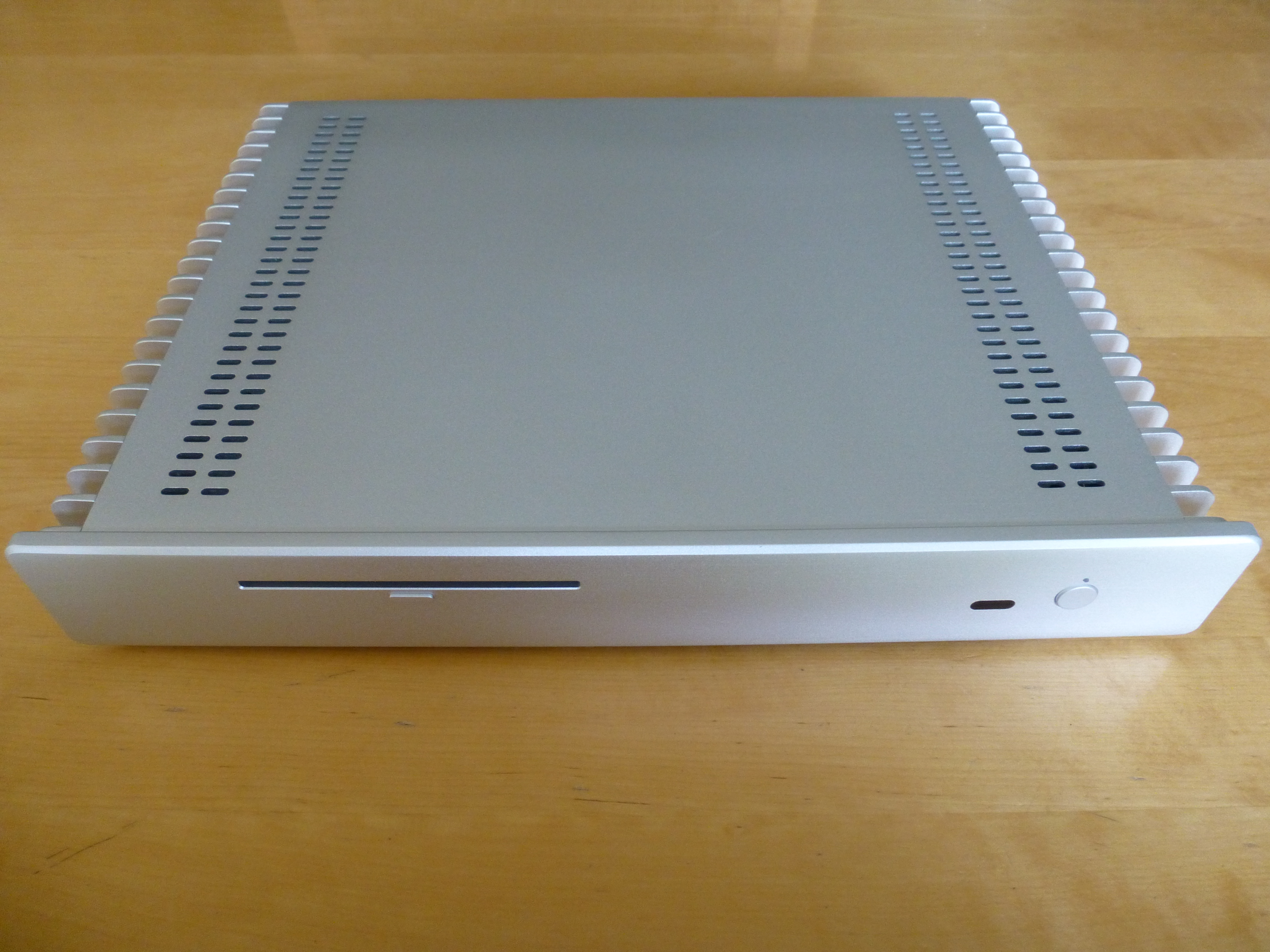
Chassis
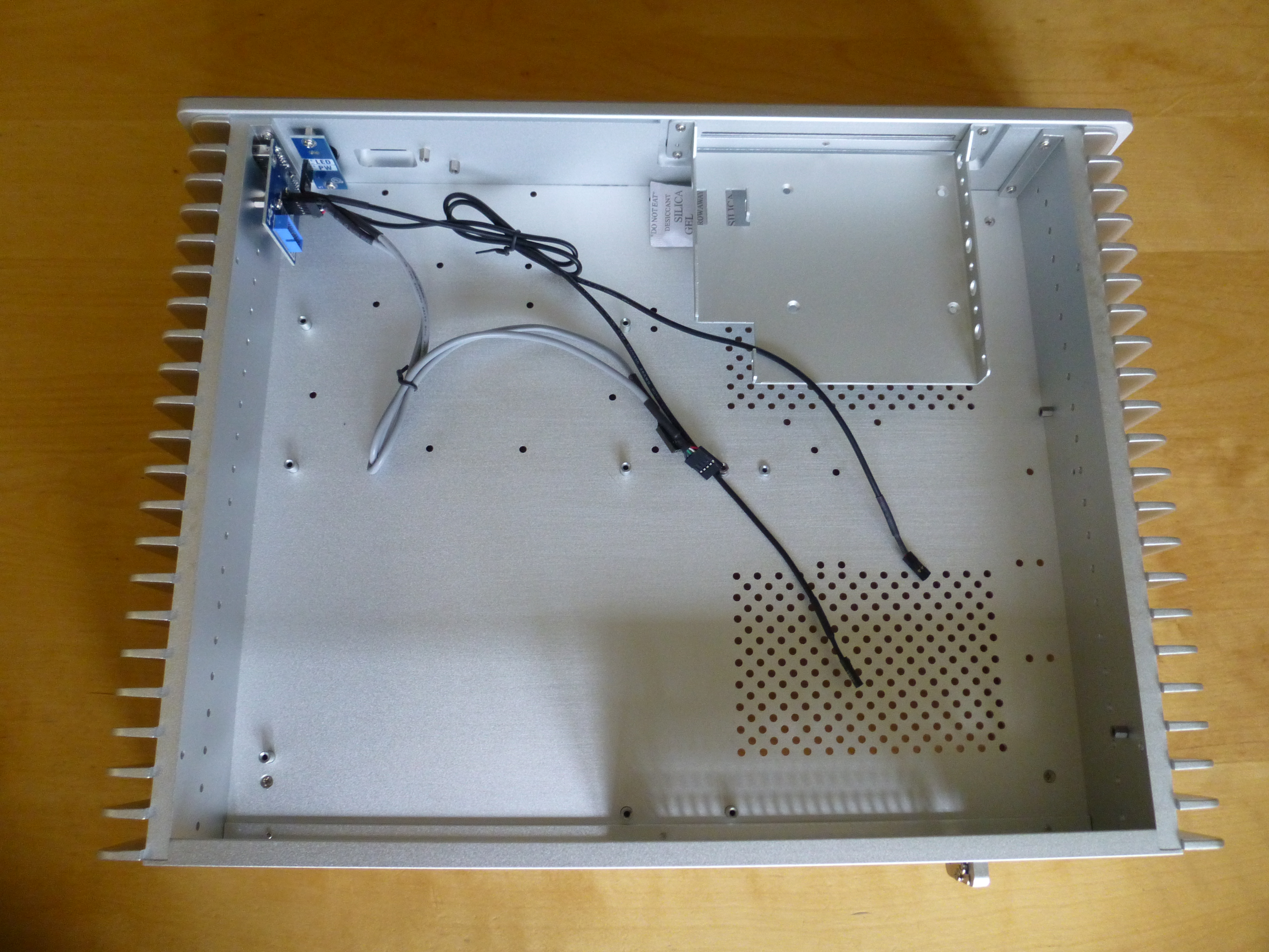
Bare internals – usb & power button cables
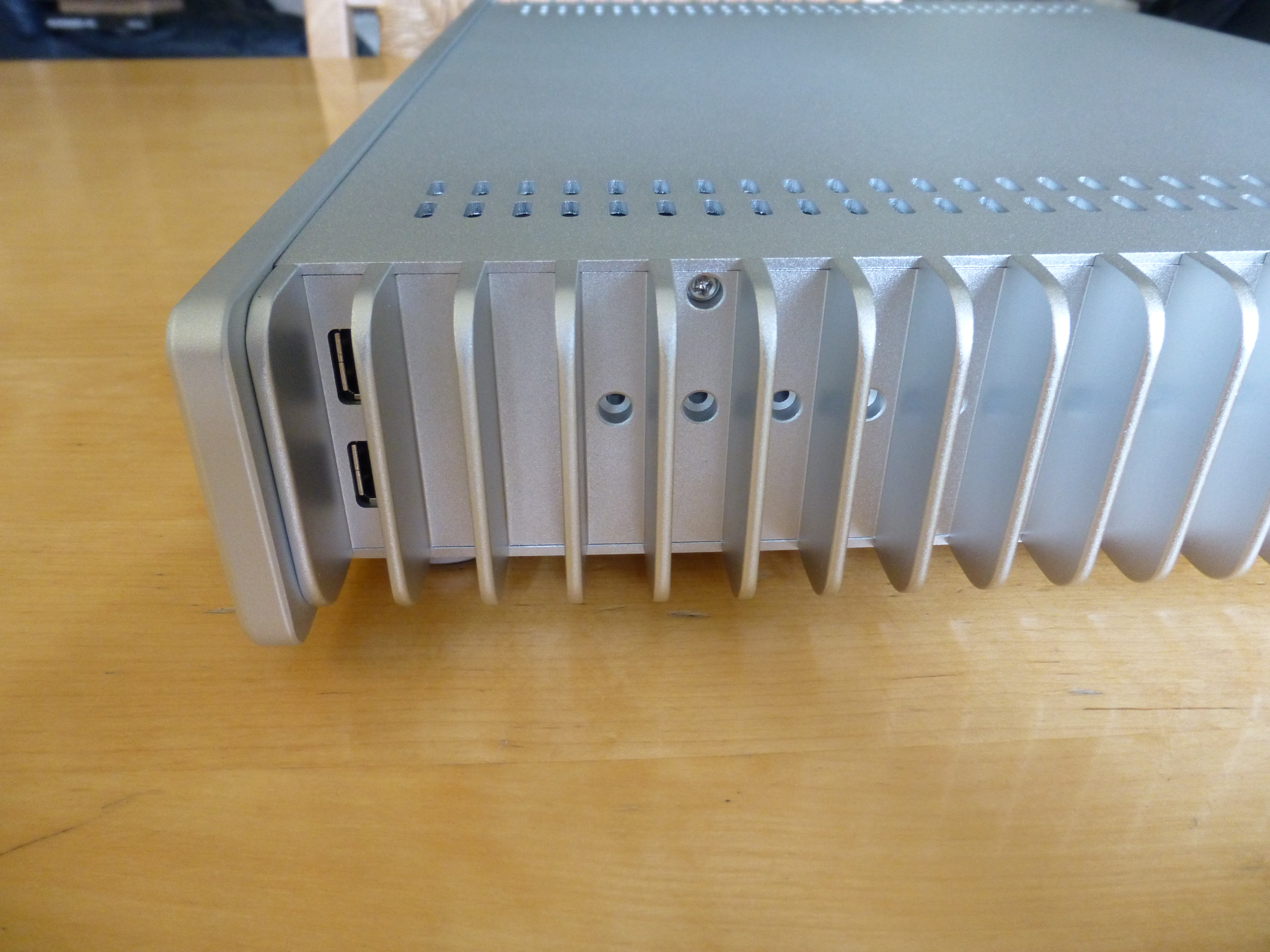
Side view with usb 2 ports
Streacom make a number of computer audio cases for HTPCs that are very suitable since they are fanless and look like proper HiFi. I went for the Streacom FC5OD EVO Silver Fanless HTPC Aluminium Chassis as it has a low profile and can fit a lot of things inside – up to three storage drives, one PCI card and an optical drive. It requires a Mini-ITX or Micro-ATX motherboard which are smaller than the standard ATX size.
It is made from thick aluminium with symmetrical heat-sinks down either side. The CPU is connected via heat pipes to the heat-sink at the back right. You can touch it in operation, verifying that heat is being dissipated. It weighs 5.2 kg, feels like a quality piece of kit and doesn’t look out of place on a HiFi shelf.
PSU
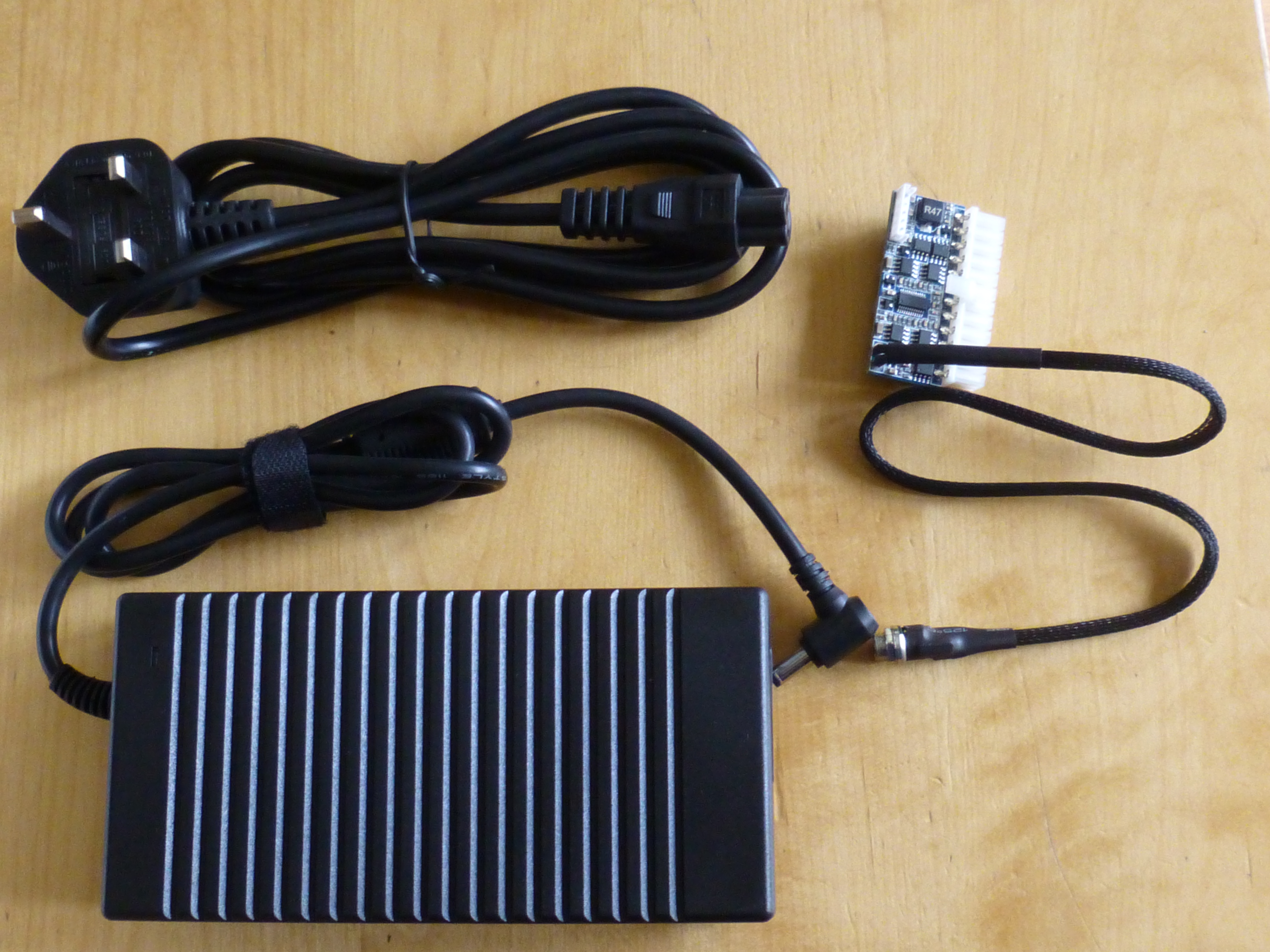
Streacom Nano150 PSU
The power supply is a Streacom Nano150 PSU. This is quite an expensive unit, but it is completely silent (no buzzing whatsoever) and designed to integrate with the chassis; the small circuit-board shown to the right connects to a socket in the back of the case and the power block has a plug that connects from the outside.
There are higher power blocks available, but this one occupies little space inside the case and the 150W is enough to drive a low power PC without a graphics card. A drawback is the large external power block. Streacom have recently released a more costly 240W supply that fits inside the case, but I have not checked if all the other components could be arranged around it.
CPU
Intel i3-4360T
In some ways, this is the most interesting component to choose. My criteria were finding a balance between:
- Low power consumption
- High single thread performance
- Cost
- Availability
- Compatibility
- On board graphics
Why do I need a high single thread performance? Well, the SRC Upsampling Algorithm is not multi-threaded.
The chip I went for is an Intel Haswell refresh i3-4360T @ 3.2 Ghz. The T suffix means low powered and it is only 35W max – most of the time it doesn’t get anywhere near this. Runtime stats give the single thread performance at 1911. This compares very favourably with my first generation i7 desktop processor: an i7-930 @ 2.8 Ghz with a single thread performance of 1209. This is able to run the best sinc upsampling algorithm at 192 kHz using 80% of one thread. It has a slight drawback of a 130W power consumption.
Looking at single thread performances in general, the current top of the tree is a 4Ghz Intel processor at 2535. The normal power consumption version of my chip, an i3-4360 @ 3.7 Ghz has a thread performance of 2181. The low power equivalent is not a bad performing chip at all, in fact the reason I chose it was because it is the most powerful single thread 35W Intel processor. It is also significantly cheaper than i5s and i7s.
When running, the passive heat-sink can easily cool this processor; the highest viable processor power quoted for the case is 65W. Just checking at the time of writing, the player has been going all day, the motherboard and processor are operating at 37 degrees celsius. The back right heat-sink is warm but not uncomfortable.
In terms of power consumption, if the directory /sys/class/powercap/intel-rapl/intel-rapl:0 represents the overall system power (some googling came up with this I’m not certain what it actually represents), then polling an energy output file (in micro-joules) at one second intervals using:
cat energy_uj ; sleep 1 ; cat energy_uj
gives a running power consumption of 7.9W which is excellent, even if it is just for the CPU, far less than 35W. My older desktop doesn’t have the capability to measure this.
Motherboard

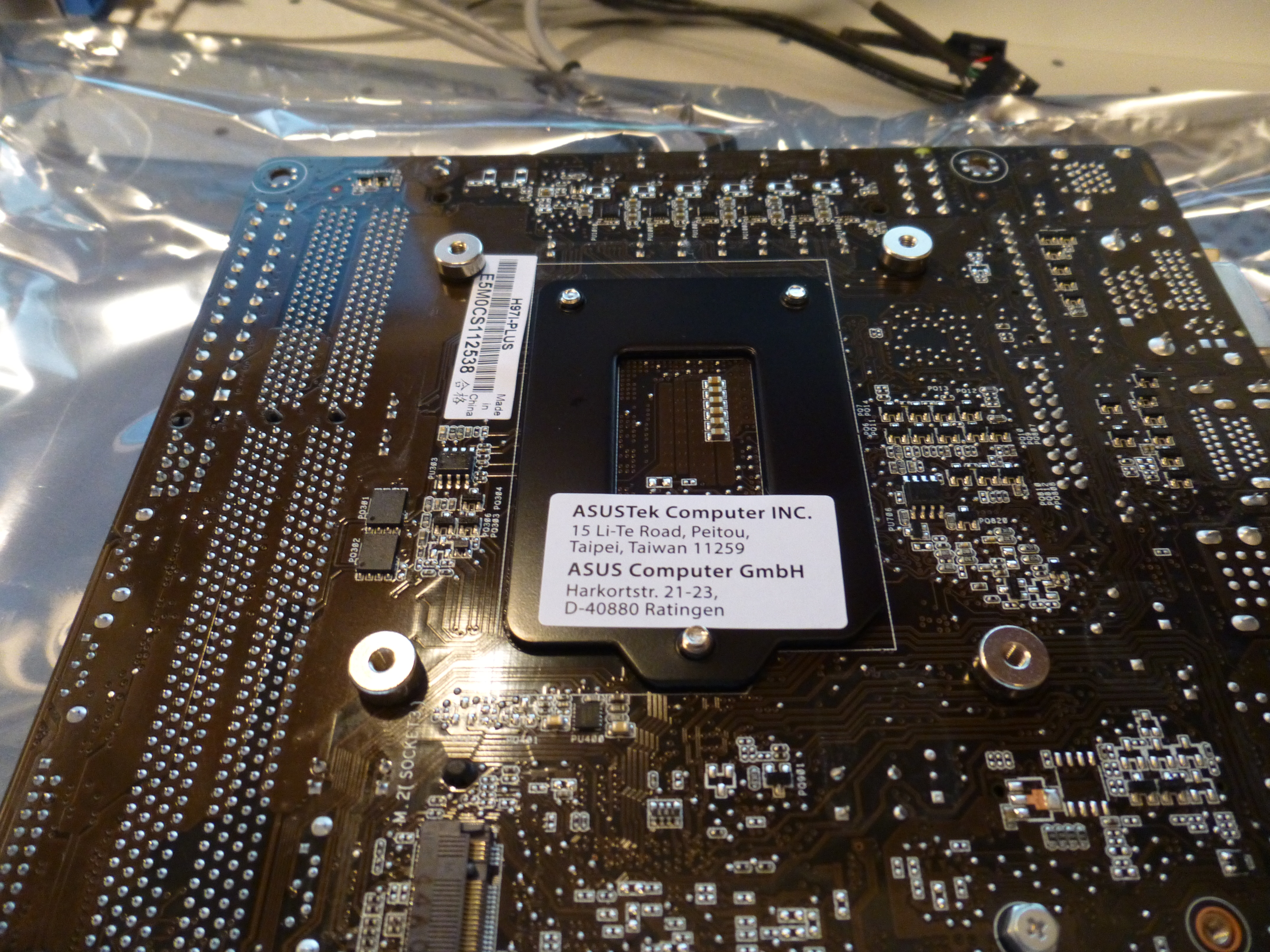
Hmm, what brand was this?
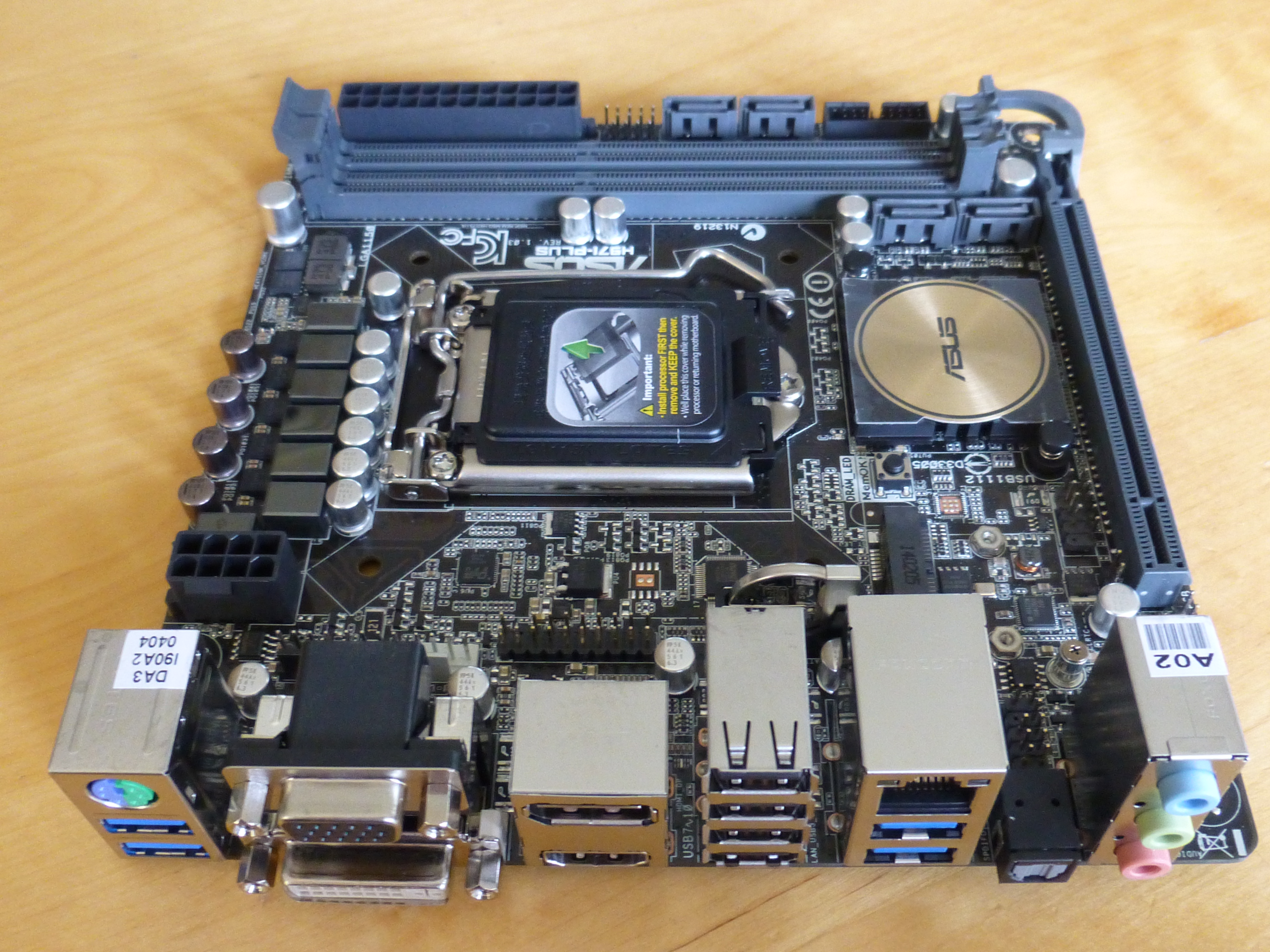
Here I admit to quite a bit of bias, I just like Asus stuff. I’ve got on well with it over the years and their high end equipment just seems to work for me. They also are quite keen on audio. I only wanted one PCI card so a mini-ITX board was fine. I just picked the best / most recent one that was compatible with the i3-4360T. This was the H97I-PLUS.
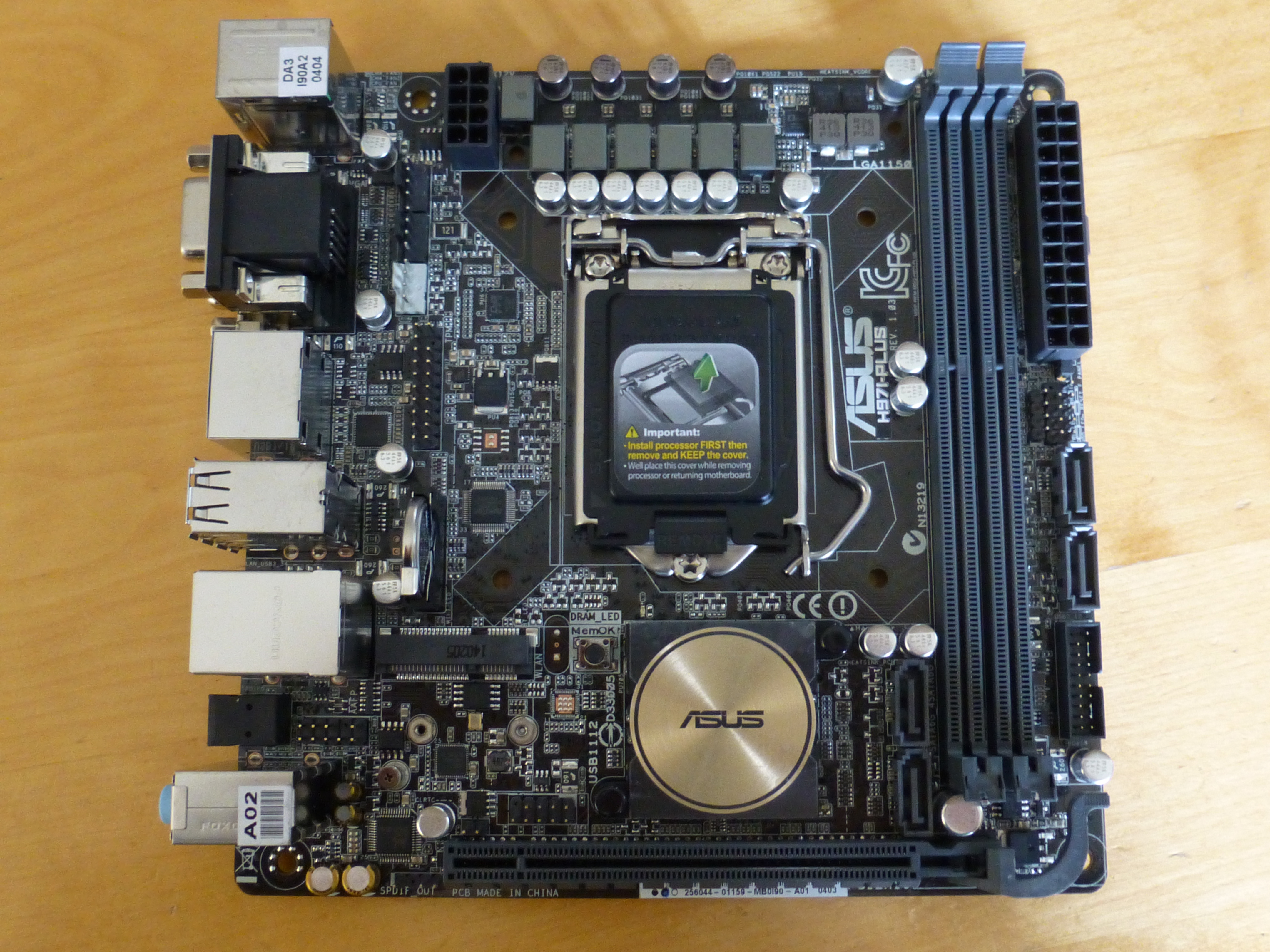
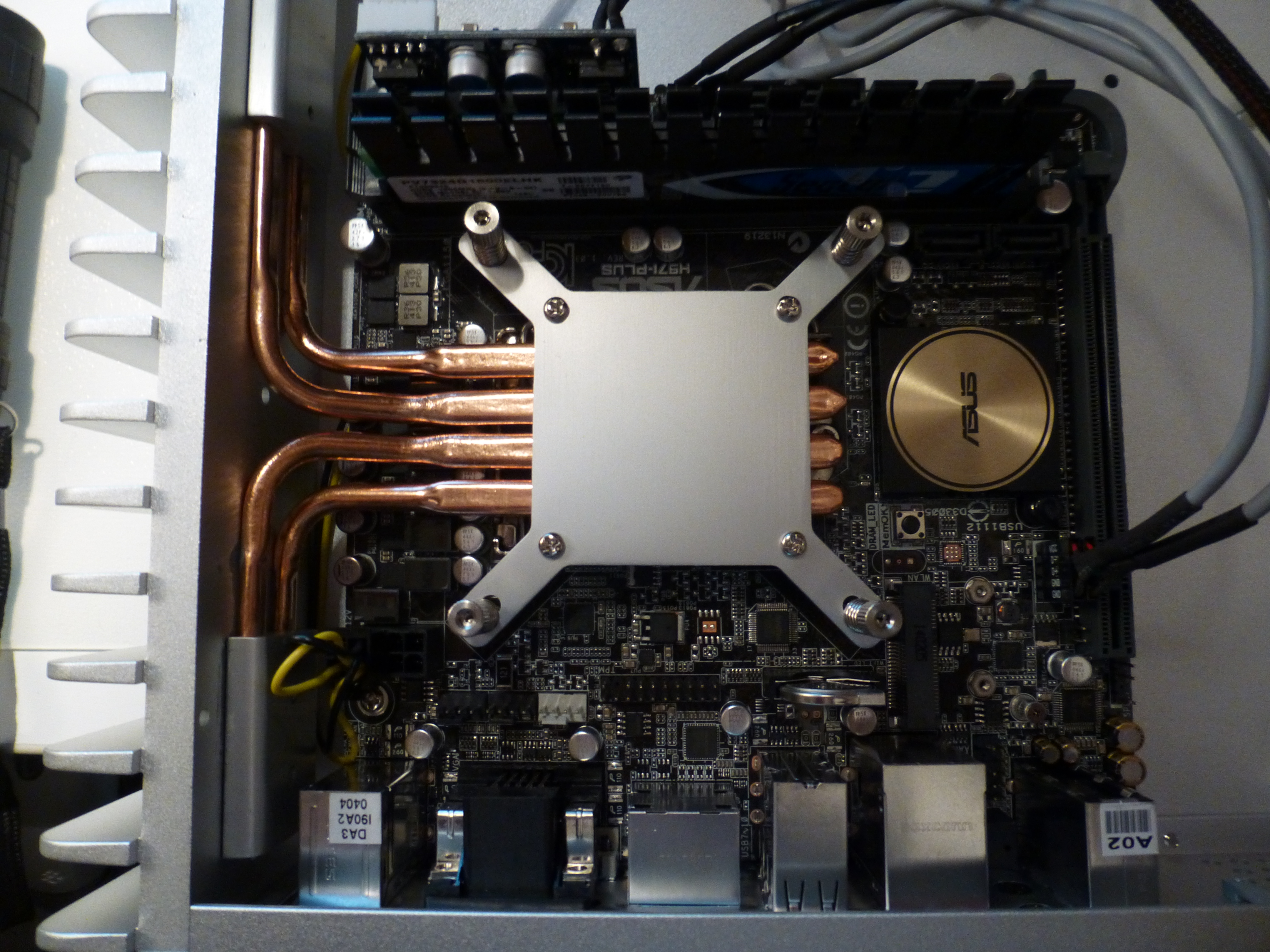
Asus H97I-PLUS
This is a compact motherboard – looking at the picture the memory slots are to the right, the external I/O is to the left. The most important thing with regards to this build is that there is enough clearance at the top for the heat pipes. Streacom has a hardware compatibility chart, but the boards are not the latest generation. Therefore I had to use powerful estimation methods (guesswork).
There is a Z97I-PLUS board that is a little more expensive but does not have this clearance. The gaming oriented MAXIMUS VII IMPACT is blocked at the back as well.
I looked at lots of boards and pictures of how the heat-pipes were fitted in other cases and hoped that my judgement was ok. For anyone else, I can now vouch that this board is fine for this case. If you look at the top, you can see there are a load of power supply capacitors which the pipes can comfortably clear. The Asus website has great pictures.
In terms of the ability to research technologies, this board has loads of features including M.2 support and a zillion connections. I know I’m only using a fraction of its capabilities, but this project is all about over specification!

Disk Drives
Wanting fast start up but also high data capacity, I went for an inexpensive 120Gb Samsung SSD and a WD Red 3TB HDD.

Oh! The noise.
These are not the most exciting of devices, but the 3TB HDD seems to be around the sweet spot of price / TB at the moment. This is the only device that makes any noise in normal operation, but it is not audible across the room when music is playing. After experimenting with trying to get it to spindown, I found something saying that WD Reds don’t provide the ability from the Linux hdparm utility. Further investigation needed, but it may be better to get a WD green or something else that can do this. I got the red because it is supposed to be able to operate as a NAS drive, being permanently running. It’s not fast, but that’s not a problem for this application.
Luxuries
An Asus Soundcard
The whole project is a bit of a luxury from the computer side, but from the HiFi perspective, it is a complete bargain. Anyway, there is an optical drive that goes with the case – I got the least expensive one as I don’t need Blu-Ray. This model is not produced any more, but one site had a load so I was able to get one. It has the eject button at the side but the case has it in the middle. There is a bit of metal that spans the whole slot that is supposed to press the button once you have added a squidgy spacer to it, but it doesn’t work for me. This is a shame as it is why I got the allegedly correct one. I solve this using the Linux eject command, but still.
The optical drive allowed me to install an operating system from a DVD, and it may one day allow me to play CDs, if I can get a command line player working, but that’s not a major problem.
The other luxury is a soundcard. It may appear essential, but the long term usage of this device is to output music via USB. However, this was not a preconception and I wanted to experiment with a soundcard. I got a recent Asus one that is super expensive for what most people would think of as a soundcard, probably quite trivial in the arena of high end audio. It is an Asus (again) Xonar Essence STX II. This has an analogue stereo out; another model adds a second card with surround outputs, but for this project it is neither desirable nor feasible as the case only has room for one PCI card output.
The card has loads of blurb about amazing features etc., but I’m only really interested in the clocking abilities and the coax & optical spdif out. The DAC is kind of irrelevant as the whole point of this is to use an external HiFi DAC with high sampling rates, but I wanted to play :).
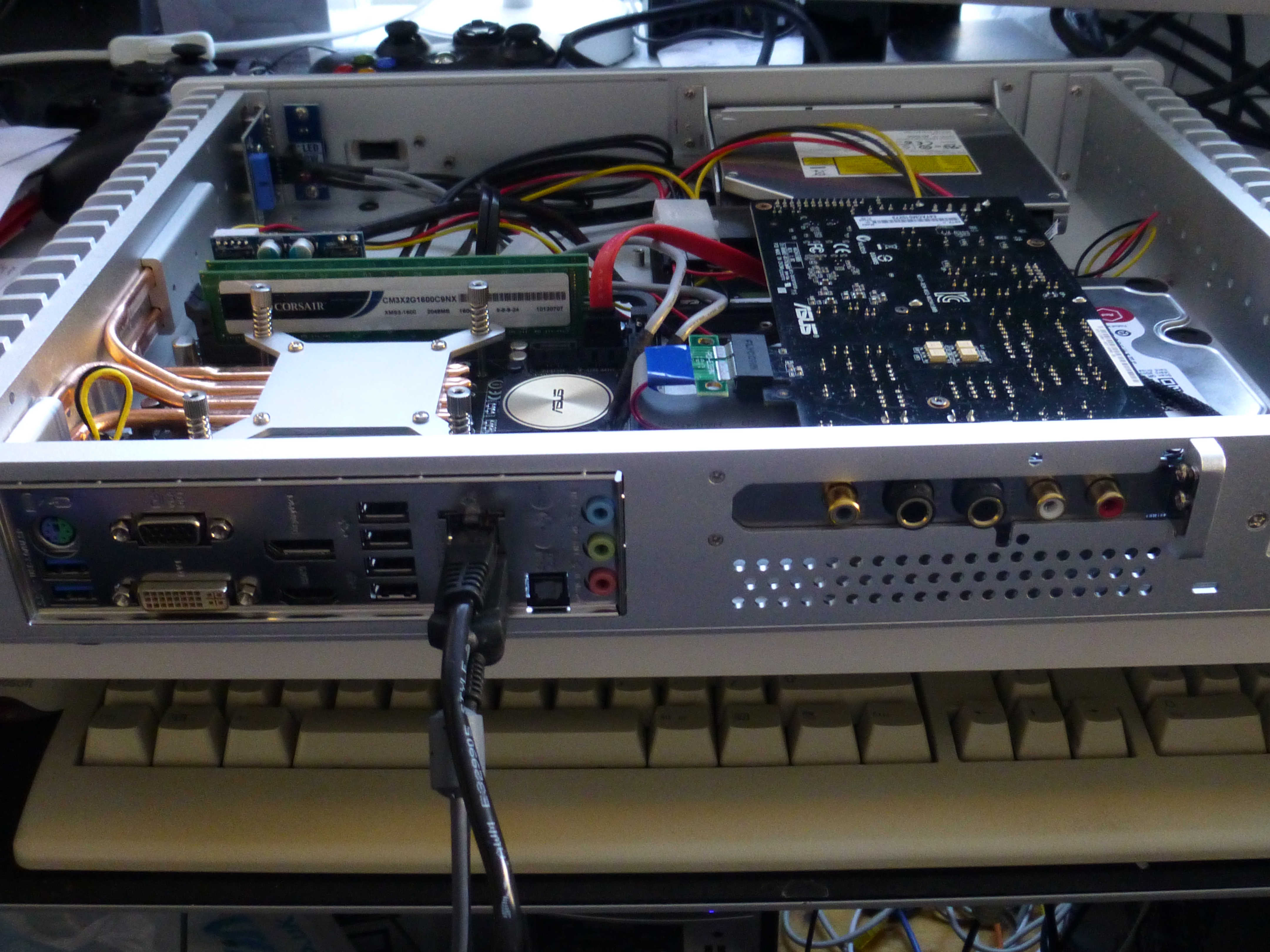
As the case is so shallow, the card cannot be sited upright and needs a ribbon cable extension to allow it to sit parallel to the motherboard.
RAM
In the picture of the components above, there is a 4Gb, 1.6 Ghz DDR3 RAM stick I took from my desktop PC as I’m not sure I use 20Gb all that often. This did not fit in the case since the heat sink on top is too high! I dug around though some old stuff and found the original RAM from my desktop before the upgrade and put two 2Gb sticks in. They seem to do the job.
Assembly

Fitting the motherboard’s back plate
This didn’t take all that long, but I built it in stages, testing what could be done at each point in order to not mess things up if a component was faulty.
First, fit the back plate from the motherboard. This was very plasticky and cheap, I was hoping for metal, but it seems to function adequately.
Fit sockets for heat-sink
Next, fit the sockets for the heat sink to the underside of the motherboard using the stickers. These have covers that have to be peeled off.
At this point, the motherboard can be fitted inside the case with the back connectors slotting into the back plate.

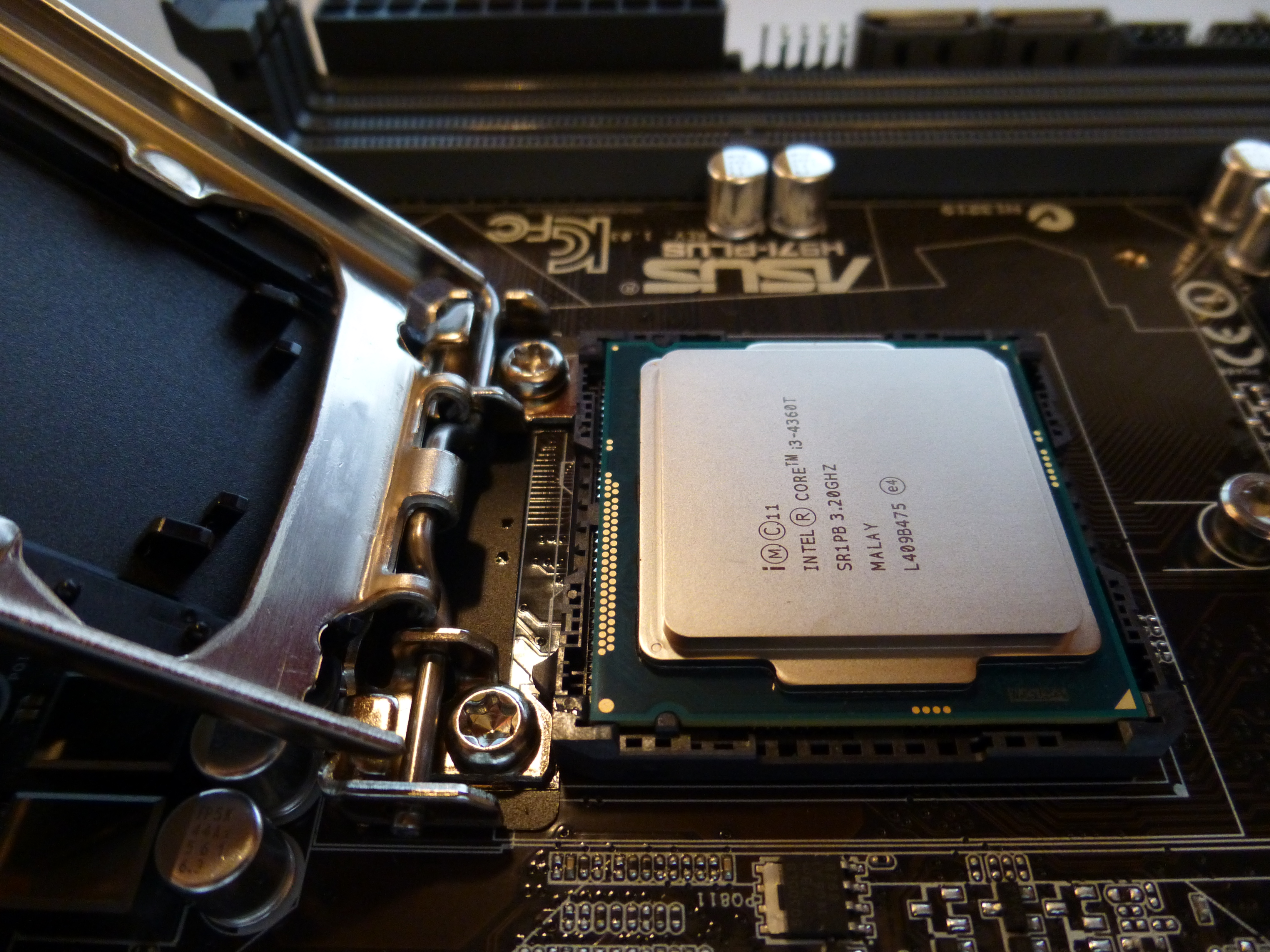
This is where the CPU goes
Now, following the instructions, open up the cpu socket and remove the plastic cover. The cpu has loads of pins on the bottom that fit into these tiny holes. There is only one way to orient the CPU correctly so put it in and close the clamp.
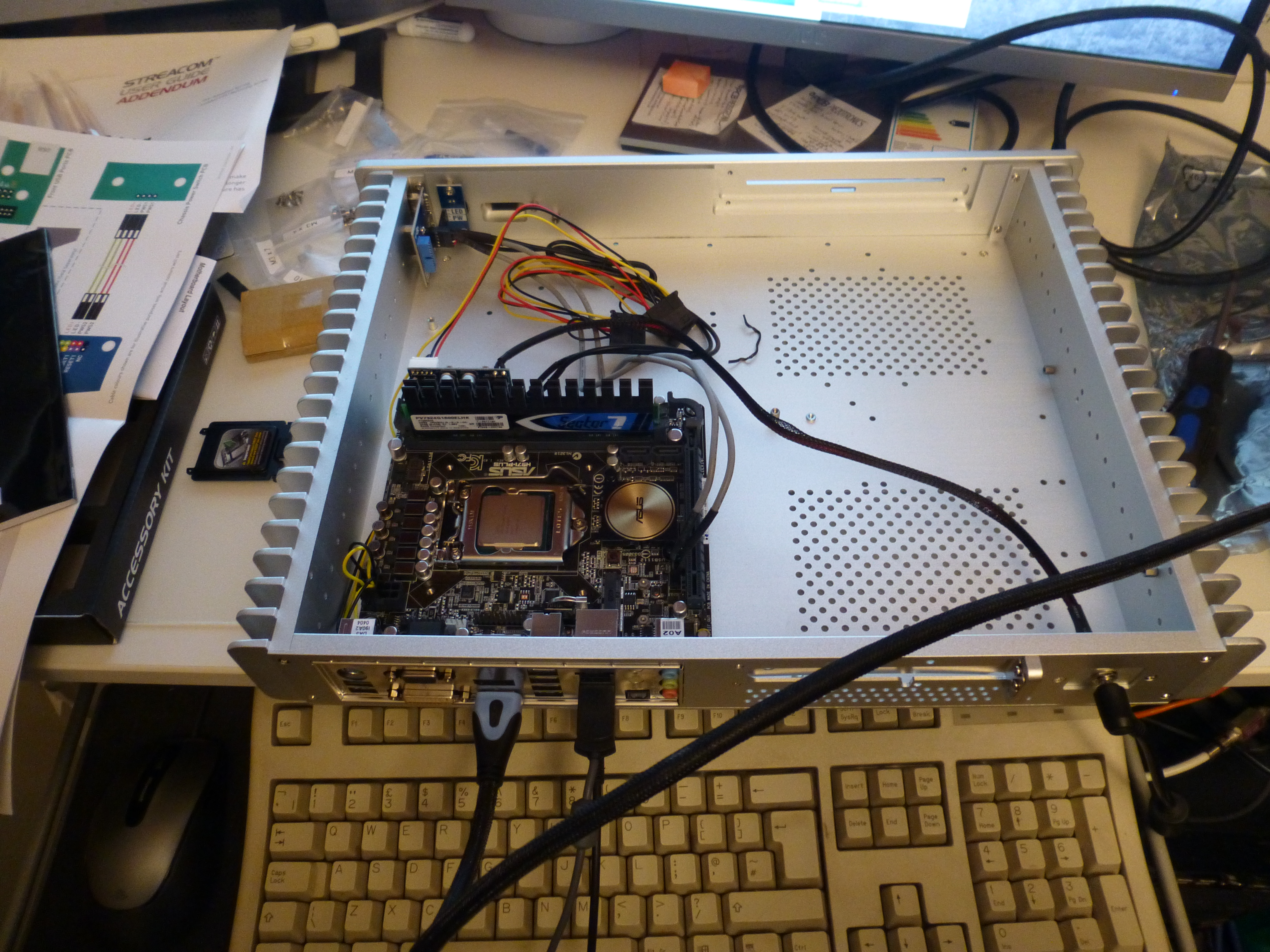
Preliminary testing
Now we can slot in the RAM stick (notice the heat sink sticking up) and the power supply. This has two connections, the main board with the capacitors on it goes at the top of the board (in this view) into the 20 pin ATX socket, the 4 pin CPU power goes into the 8 pin socket at the bottom left. This is fine and there is only one of the two places where this fits properly. Zoom into the picture to see how it is supposed to go. The cable should go under the heat-sinks. If you like, you can pull it completely under the motherboard, but then you would have to remove everything if you need to change the power supply.
Connect a monitor, keyboard and mouse, and fire it up! Just long enough to check that the components installed so far are functioning. As there is no cooling, the heat progressively increases – I think it hit around 57 degrees C before I shut it down.
Now the heat-pipes
To fit the heat-pipe assembly, first clean the parts with some solvent. I have a pack with some in including some thermal paste lying around from previous builds. I used the paste that came with the Streacom kit. Put a rice grain sized blob on the CPU and then place the lower part of the heat-sink assembly on top. Then comes the tricky part, the heat pipes are all different lengths (so you need to figure out which goes where) and you have to put thermal paste in the troughs on the heat-sink and on the part of the pipes that touch the wall. The objective is to guide the heat via the paste to the side of the case, so we won’t put paste on the upper side of the pipes, nor on the outer side where they touch the wall.
Fortunately, the paste is sticky, so you can place the pipes where you need them to go and make small adjustments. Nothing is screwed in at this point, so it is a bit fiddly, but not at all impossible.
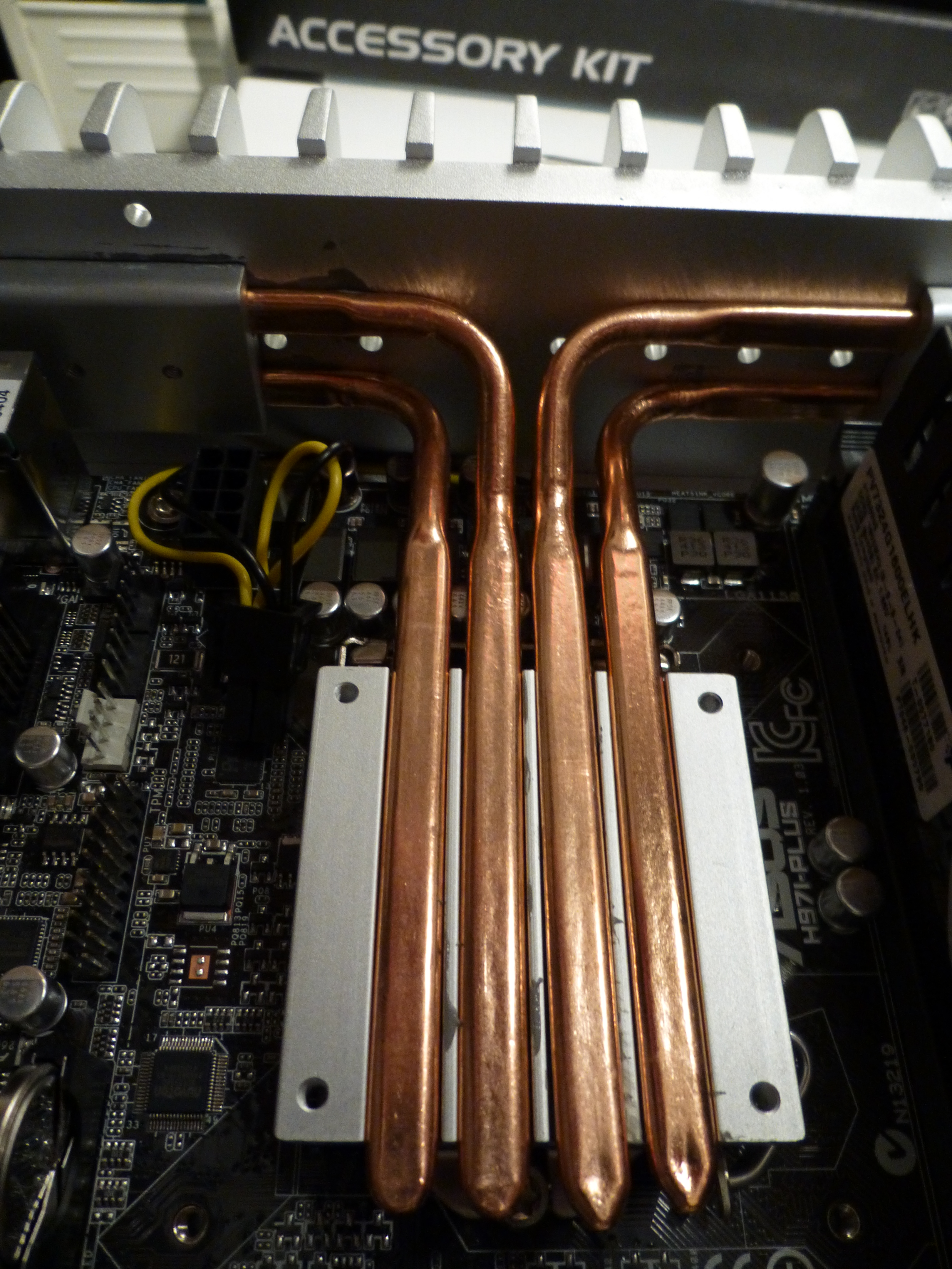
Screw the heat pipes down
Now screw down the heat-pipes and attach them to the wall using the plates as shown and a couple of Allen keys. Watch out for the 4 pin power cable and tuck it down so it doesn’t touch the pipes.
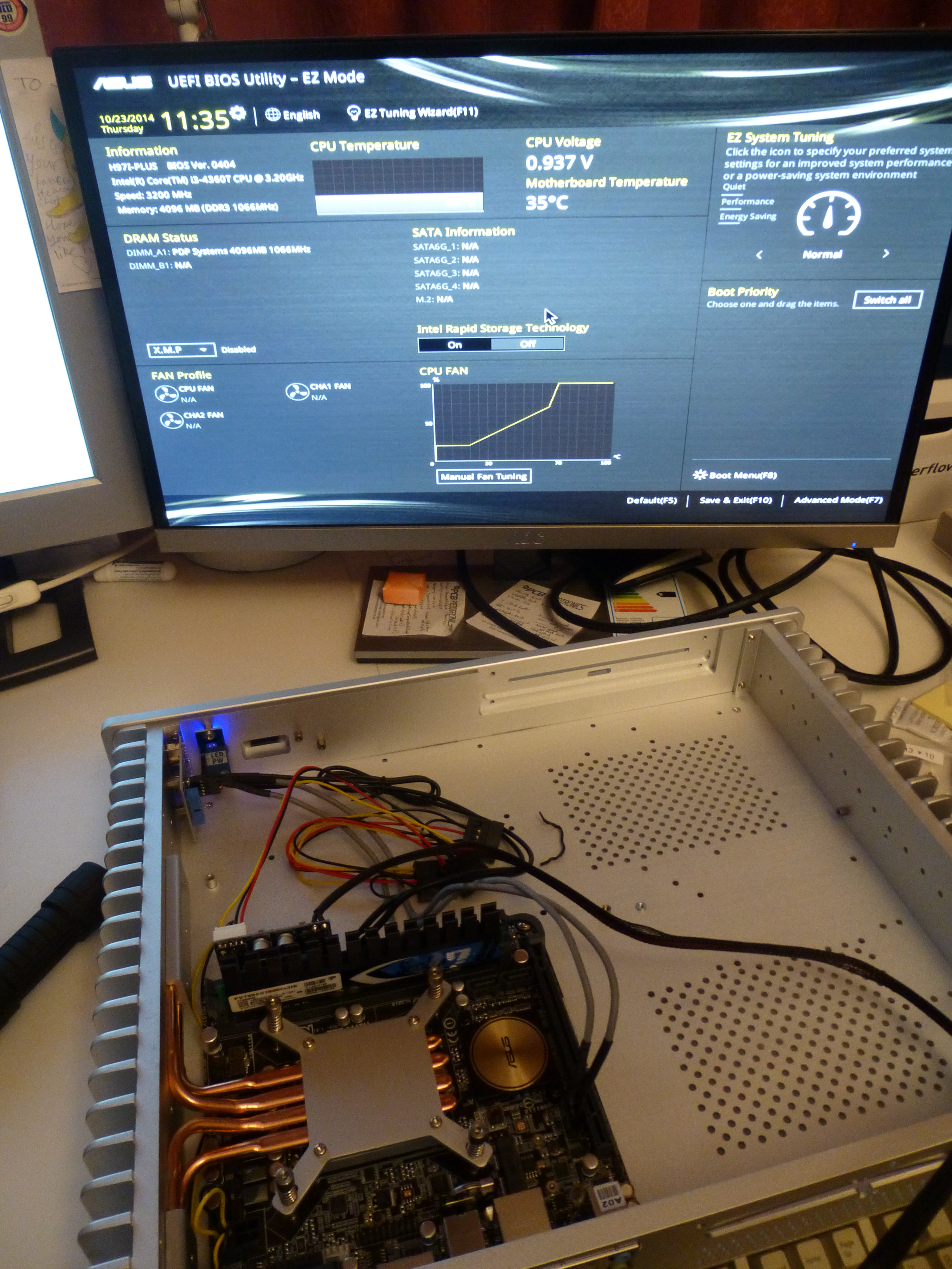
Fire it up again
This should now be a stable functioning system so start it up again. This picture is showing the UEFI Bios screen. The temperature is stable at around 35 degrees C. I left this overnight just to check that everything was ok. As a brief aside, it wasn’t. The next morning, the system was dead. This was diagnosed (with the help of a multi-meter) as the power supply brick. It was not supplying 12v, so had to be replaced, which meant removing all the power supply components from the motherboard and returning them as well.
Add in the other components
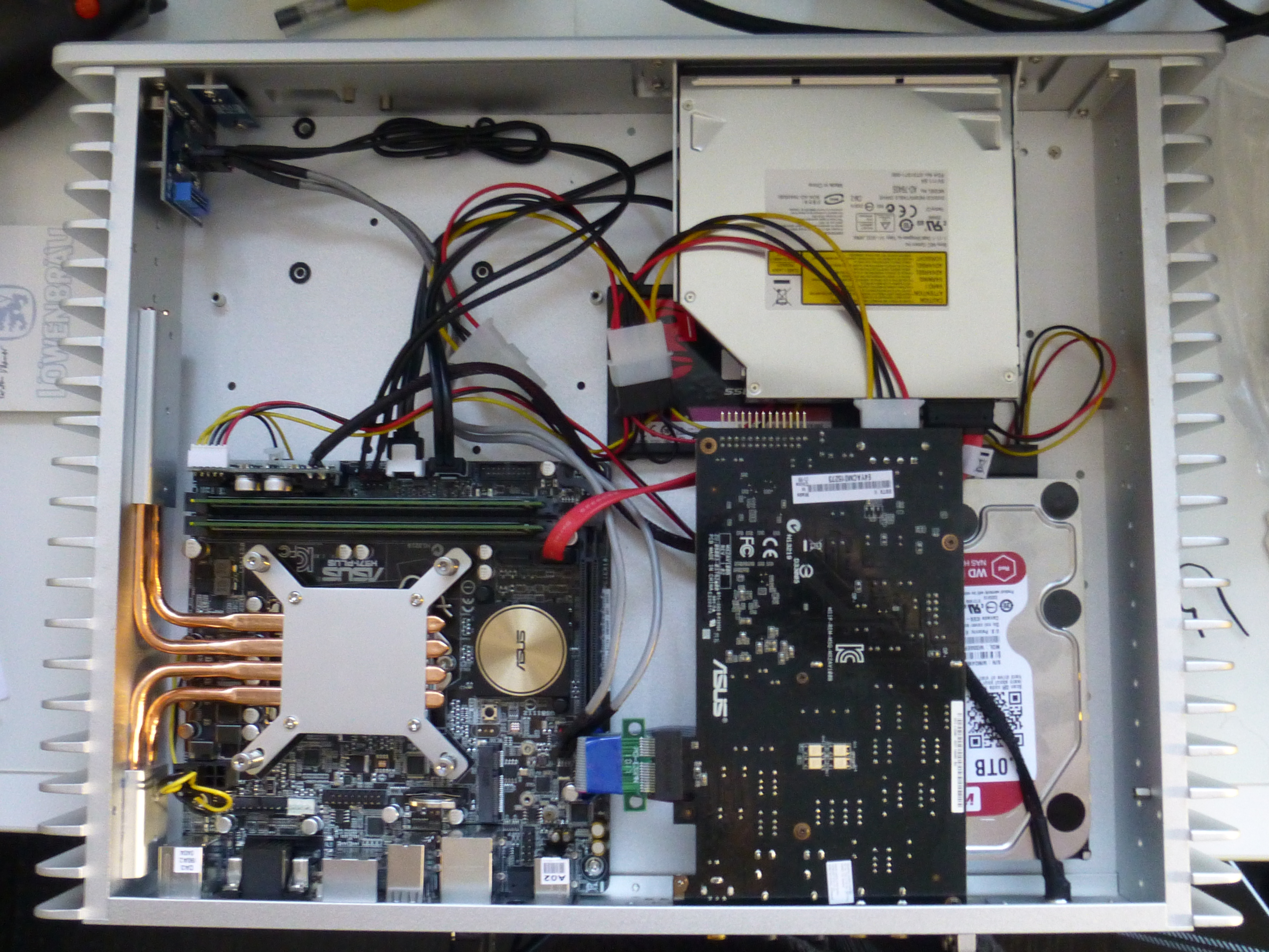
Adding in the other components, the SSD and HDD are screwed down to the base of the case using squidgy spacers that absorb vibrations. At first I put the SSD too far away for the cabling to connect so I had to move it closer. I also needed a molex splitter to have enough connectors to power all devices. The sound card and optical drive go above the drives. Connect the sound card horizontally using a PCI x1 ribbon cable.
Here is the complete build, with the RAM replaced by the lower profile cards:
Everything in place
Next
In an upcoming article, I will describe how this can be configured to run mpd. I’ve figured out how to avoid having to use pulseaudio, so stay tuned!

luigi rensinghoff
/ January 4, 2015Hey that’s really quite exactly what i was trying to configure myself – Do you mind if i get in touch with you (PM) – I would be interested in the allover price – and possible pci-expansion.
You can send me an e-mail to
mdhalien
/ January 6, 2015I think this cost around £800 – but this could easily be reduced by changing or removing some of the components, especially the soundcard that I don’t really use. Prices change daily so best to shop around. There is only one PCI socket and I’m using it with the card which must be mounted horizontally, so you need to use a ribbon cable to connect to the motherboard. This case only supports one PCI card. Other Streacom cases have different I/O requirements (fc09 has 3xlow profile, fc10 has 2x vertical full size).
slots online
/ January 14, 2015Hello webmaster, do you allow guest posting ?? Please let me know, i’m interested .
mdhalien
/ January 16, 2015Sorry, this is just some ramblings I come up with – set up your own blog! It’s easy with wordpress.
Cheap Handheld Gps
/ February 8, 2015Hey I am so happy I found your weblog, I really found you by accident, while
I was searching on Google for something else, Anyways I am here now and would just like to say thanks for a tremendous post and a all round exciting
blog (I also love the theme/design), I don’t have time to read
through it all at the moment but I have bookmarked it and also added in your RSS feeds, so when I
have time I will be back to read a great deal more, Please do keep up the superb jo.
gt racing 2 hack free download
/ February 22, 2015Hi, just wanted to mention, I enjoyed this post.
It was practical. Keep on posting!
Fidelia
/ June 14, 2015There’s definately a lot to know about this subject. I love all of the points you made.
gt racing 2 cheat
/ June 16, 2015I’m extremely impressed with your writing skills and also with the layout on your blog.
Is this a paid theme or did you customize it
yourself? Either way keep up the nice quality writing, it
is rare to see a nice blog like this one these days.